Saturday, 26 September 2009

Bluetooth scanning experiments

This was never supposed to be exclusively a RepRap blog, I've just never posted anything else on it before, so here goes.

I moved into a new flat that is above a high street, and noticed that there were always a lot of bluetooth devices (phones) around when I looked in the Gnome bluetooth applet.

I created a simple script that continually scans for devices and reads out people's bluetooth names out loud using festival. The next day I broke my vow to never own a Twitter account after I saw how simple the Python API was to use, so now all the names are now posted on Twitter too.

Why? It's all rather pointless, I'm sure it's been done before, but it's an interesting experiment and emphasises the privacy concerns of having your phone continually shouting out "me me me" with a unique identification number (MAC) to anyone who wants to know. I also observed that many of the bluetooth names are actually just set to the phone make and model. It's probably not the best idea to have you're rather expensive phone advertising itself as "BlackBerry 8120" or "Nokia N95 8GB".

You can see the full source here.Link

Sunday, 28 June 2009

Spider Grip

My mini Darwin design does not have enough space to put the Z axis motor in-line with one of the treaded rods, so from the beginning I had been thinking of placing the motor along one of the side rods. I have been trying to think of a good way of mounting the motor for a while now, then a few days ago I had the idea of making this 'spider grip' (it looks a bit like a four legged spider).

hpim1758.jpg

The 'legs' arch up before going to the 'body' to give some elasticity, so that when the screws are tightened the rod is held very firmly against the motor.

hpim1759.jpg

Here it is fitted to the machine. It gives a very firm grip, however it can be twisted fairly easily around the axis, but is firm enough to keep it in place. The only forces that will be applied to the motor when in operation are a liner force along the length of the chain, and a rotary force around the motor spindle, so no force should be present in the one direction that the motor can twist.

hpim1763.jpg

I've just put a load of closeup pictures of the machine onto my flickr page.

hpim1768.jpg

Unfortunately I've just broken my extruder, but more about that next.

Thursday, 25 June 2009

Broken extruder

I broke my extruder!

I have used my extruder with CAPA before and it has been reasonably reliable, though I was never able to get any filament (I just rolled some bits). I gave up on trying to get any and so I recently purchased some ABS.

I put the ABS into the extruder, heated it up, and ran the last of the CAPA out. I turned the temperature up on the extruder, but was unable to get past 159 degrees. Eventually I decided that the temperature was not going to get any higher so I tried to run the ABS through anyway.

In the past the motor has stalled quite easily at low speeds when the extruder is not hot enough, but this time it didn't stall and instead pushed the heater barrel out of the PTFE rod. Presumably this is because I have never had the extruder this hot before.

HPIM1750.JPG


HPIM1752.JPG

I ordered some PTFE rod, some brass bolts, nichrome, thermistors, thicker cable (for connecting heater to board), drill bits and an M6 tap. This should be enough to make a few experimental barrels, although I'm not yet sure how I'm going to do this without a proper pillar drill or lathe.

Monday, 18 May 2009

CAPA fixes everything!


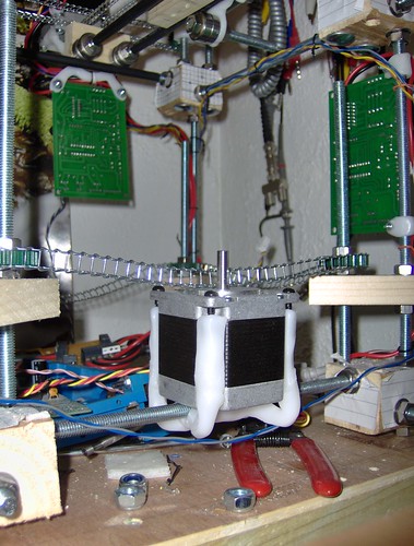
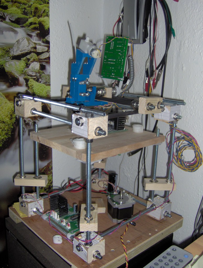
I've made a bit more progress with my mini Darwin. I now have an X axis with the extruder mounted on it, as well as a more or less complete Z axis. When pushing the extruder around it moves very smoothly, and with very little force so I'm hoping to get some pretty decent print speeds and much better quality than my Lego RepStrap. My idea with this RepStrap is to put in the least amount of required effort to get the thing of the ground, I'm not really designing the thing to last. Then once it is printing I can replace the lower quality pieces with new printed parts!


A quick note about drills
I did not use a pillar drill for my corner blocks, I just used an electric hand drill and a set square. The holes are more or less straight but the imperfections have caused me a lot of problems. My machine is actually a parallelogram rather than a square, but as long the the axis slide rods are parallel then this does not matter too much. I would advise anyone without a pillar drill to try and find one they can use, as the time you spend finding one will be much less that the amount of time you will spend trying the get everything straight afterwards!


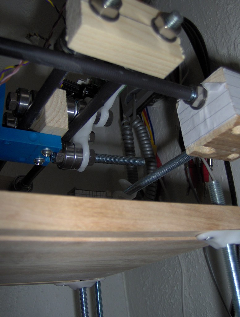
I had not realised how much the extruder would overhang on the X axis, so my idea of having a X carriage just using skate bearings on top was not going to work. A bit of CAPA moulding later and I had a nice part that holds a third bearing underneath the carriage, rolling along the underside of the steel rod. The piece was bent a little before it set so that it is sprung firmly against the rod (CAPA is very 'springy') keeping the X carriage very firmly against the rod.


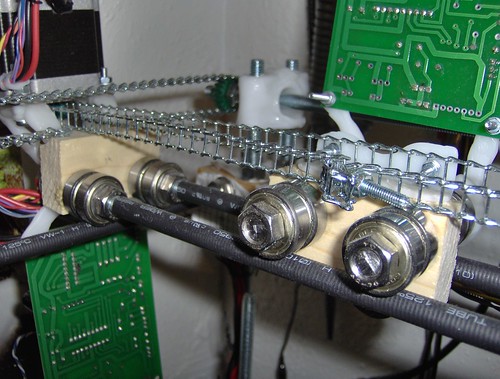
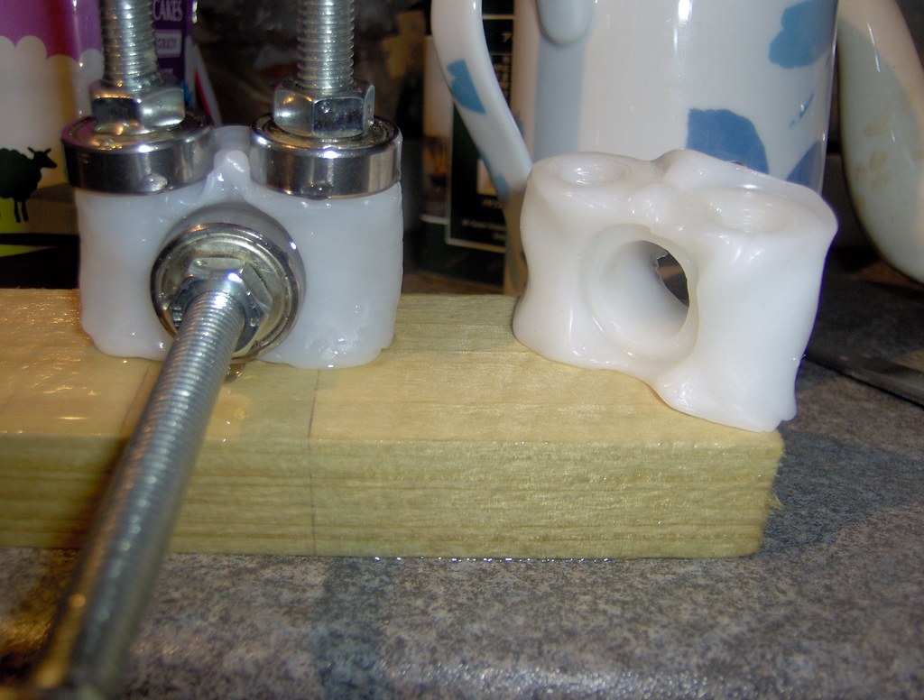
I made these CAPA brackets to hold the nuts and used just two screws in each of them to allow a little play, but only when tensioned against the twisting of the CAPA.


Building a jig first makes making parts from CAPA much easier. These are bearing blocks for the Y axis using 608 skate bearings. They may not look precise, but the three holes are, and that is all that matters :)

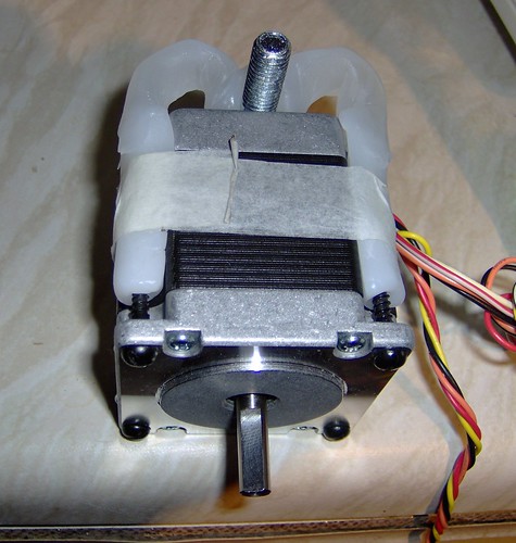
Now I'm just waiting for my gears and chain to arrive, but in the meantime I can still make my X, Y & Z motor mounts. Time for some more CAPA I think.

Monday, 11 May 2009

Gears and chain

I have decided to use this chain with these gears,

I will use the 15mm gears for the X and Y axes and the 40mm ones for the Z axis. For my mini Darwin I will need: Y axis - 510mm x 2; X axis - 564mm; Z axis - 972mm. This gives a total of 2556mm so I will need to order 3m.


This works out quite extensive at £30.25 for all the chain and gears but I will have plenty of gears left over (they come in a large pack) and will be happy to send any to anyone in the UK who wants any.

The motors I have are 200 steps per revolution, using a 15mm gear the axis will move 47.115mm per revolution. This gives an axis resolution of 0.24mm which I will be perfectly happy with.

Sunday, 10 May 2009

Mini Darwin

I received my 20 300mm threaded steel rods with lots of nuts and washers so I set about making some corner brackets to hold them all together. I don't have a pillar drill so I just had to drill holes with an electric hand drill and a set square. This worked reasonable well but the holes were very rarely at perfect right angles. To 'fix' this I used a reamer to enlarge the holes, allowing the steel rods to line up straightly. This would not work in the standard Darwin design using un-threaded rods and grub screws. However with this design it does not matter if the hole is a bit bigger, as long as the blocks themselves have right angle sides then the rods will line up when the nuts and washers are tightened. While not elegant, it works.

A mitre box is essential

I also used soft wood, again because of the threaded rods, the blocks become stronger when they are assembled.


Four blocks ready for drilling


The assembled frame

The Y axis moves very nicely on the shrink-wrap covered threaded rod. Next I need to get some chain or belt, and make the Z axis and print table.

I think 300mm rods may have been a little small and will give a very small [but usable] print area. I probably would have been able to get away with some smaller motors too as the skate bearing axes require very little force to move.

Thursday, 7 May 2009

Spanner Spin


ultimate stepper testing - stepper motor spins spanner!